
Modelling of Multi-Storey Cross-Laminated Timber Buildings for Vibration Serviceability

1
Faculty of Civil and Geodetic Engineering, University of Ljubljana, 1000 Ljubljana, Slovenia
2
AI Laboratory, HUN-REN Institute for Computer Science and Control (SZTAKI), H-1111 Budapest, Hungary
*
Author to whom correspondence should be addressed.
Buildings 2024, 14(3), 689; https://doi.org/10.3390/buildings14030689
Submission received: 22 January 2024
/
Revised: 27 February 2024
/
Accepted: 2 March 2024
/
Published: 5 March 2024
(This article belongs to the Special Issue Structural Vibration Serviceability and Human Comfort II)
Abstract
:In this study, the vibration serviceability of multi-storey timber buildings is addressed. The core of this study pertains to the preparation of a comprehensive finite element model to predict modal properties for an accurate vibration serviceability checking. To that end, findings obtained from studying three multi-storey timber buildings are summarized and discussed. Two of the buildings (of seven and eight storeys) consist entirely of cross-laminated timber (CLT), while the third is a five-storey hybrid CLT-concrete building. Thanks to the detailed finite element models and modal testing results, one has the capability to conduct sensitivity analyses, classical and Bayesian model updating, and uncertainty quantifications. With these methodologies, influential modelling parameters as well as the sources of modelling error were identified. This allowed for conclusions to be drawn about the in-plane shear stiffness of the constructed walls (whose higher value causes the natural frequencies to increase by up to 25%), the soil deformability (which may cause the natural frequencies to drop by up to 20%), and the perpendicular-to-the-grain deformation of floor slabs (which may lead to an overestimation of a fundamental frequency by up to 8%).
1. Introduction
The structural design of multi-storey timber buildings is often governed by serviceability criteria [1]. Understanding how to effectively meet serviceability criteria not only enhances user comfort but also contributes to reduced material consumption and more cost-effective design decisions. Several aspects are included in the consideration of serviceability, such as vertical deflections, lateral drifts of the walls, floor vibrations, and vibrations of the whole building [2]. The latter may cause a separation or cracking of the exterior cladding, doors, windows, and damage to interior components, or simply induce discomfort. For tall timber buildings, wind-induced vibrations of the building are often the governing serviceability criterion [3,4]. They can also be the governing design criterion, as shown for a 14-storey timber building and the Eurocode set of standards with national annexes for Norway [5]. For even tall timber structures, an evaluation of serviceability criteria for various conceptual designs, based on Canadian national codes, demonstrated the suitability of a 30-storey timber building for residential use [6].
Comfort criteria are based on the human perception of vibrations [7]. It is essential to recognize the substantial variability in individual physiological and psychological responses to identical motion levels. Different properties of motion (such as displacement, velocity, acceleration, and its derivatives) may be considered [8], and accelerations are generally used in the calculation of comfort criteria. Two standardized limit curves are adopted by two ISO standards [9]. ISO 10137 [10] restricts 1-year peak accelerations depending on the commercial or residential use of the building, and ISO 6897 [11] adopts 5-year root–mean–square horizontal accelerations as a criterion. Both standards employ a frequency-dependent curve, which requires the calculation of the natural frequencies of the building. For buildings taller than 50 m, Eurocode 1 [12] proposes a simplified empirical equation to calculate the fundamental frequency (in hertz) by
where h is the height of the building (in meters). However, to accurately calculate modal properties, an advanced modelling approach is indispensable. Illustrative examples of comfort criteria calculations are shown for the case of cross-laminated timber (CLT) and glue-laminated timber (GLT) buildings according to the Swedish [13] and UK regulations [14].
The accurate prediction of modal properties is an important goal for structural engineers designing tall timber buildings. However, the desire for time-efficient solutions requires simplified methods. The reliability of the simple Equation (1) is questionable when aiming for accurate modal property predictions. Although its applicability is restricted to buildings surpassing 50 m, wind-induced vibrations can emerge as the governing design criterion even for structures of a considerably lower height [5]. A commonly adopted approach to predicting modal properties is to develop a finite element (FE) model. In the case of CLT buildings, the panels are modelled by shell elements. To streamline the modelling of the layered structure of the CLT panels, simplified shell elements have been proposed [15,16], although shell elements that explicitly model the layers of the panels can be used as well [17,18].
To an FE model, choices about material properties and modelling assumptions need to be made. Due to its non-homogeneous structure comprising cellulose, hemicellulose, and lignin, each with distinct stiffness and density properties, timber, in particular, poses a higher level of uncertainty in material properties compared to classical structural materials. This inherent variability results in a wide range of material properties. For instance, the density of Norway spruce with a moisture content of 12% is typically between 350 and 600 kg/m3, while the along-the-grain elastic modulus varies between 13.5 and GPa [19]. The complexity amplifies when considering engineered timber products, such as the CLT panels, where the uncertainty of stiffness parameters further escalates. The in-plane shear modulus, arguably the most critical stiffness parameter for the CLT panels, varies widely among European technical assessments (ETAs) of different manufacturers, ranging from 250 MPa to 500 MPa [20,21,22]. On the other hand, values of 650 MPa and 450 MPa are recommended [23], depending on whether the narrow sides of the lamellae are glued together or not. Besides the already considerable variability in material properties, the moisture content emerges as another influential factor impacting timber properties [24]. Generally, strength and stiffness decrease with the increasing moisture content [25]. However, when examining the CLT panels, the relation between moisture content and shear stiffness is reversed [26]. The drying of the panels causes cracks in the lamellae and in the bond between lamellae, resulting in reduced stiffness. Such uncertainty in material properties and stiffness translates into a large uncertainty in the predicted modal properties of timber buildings.
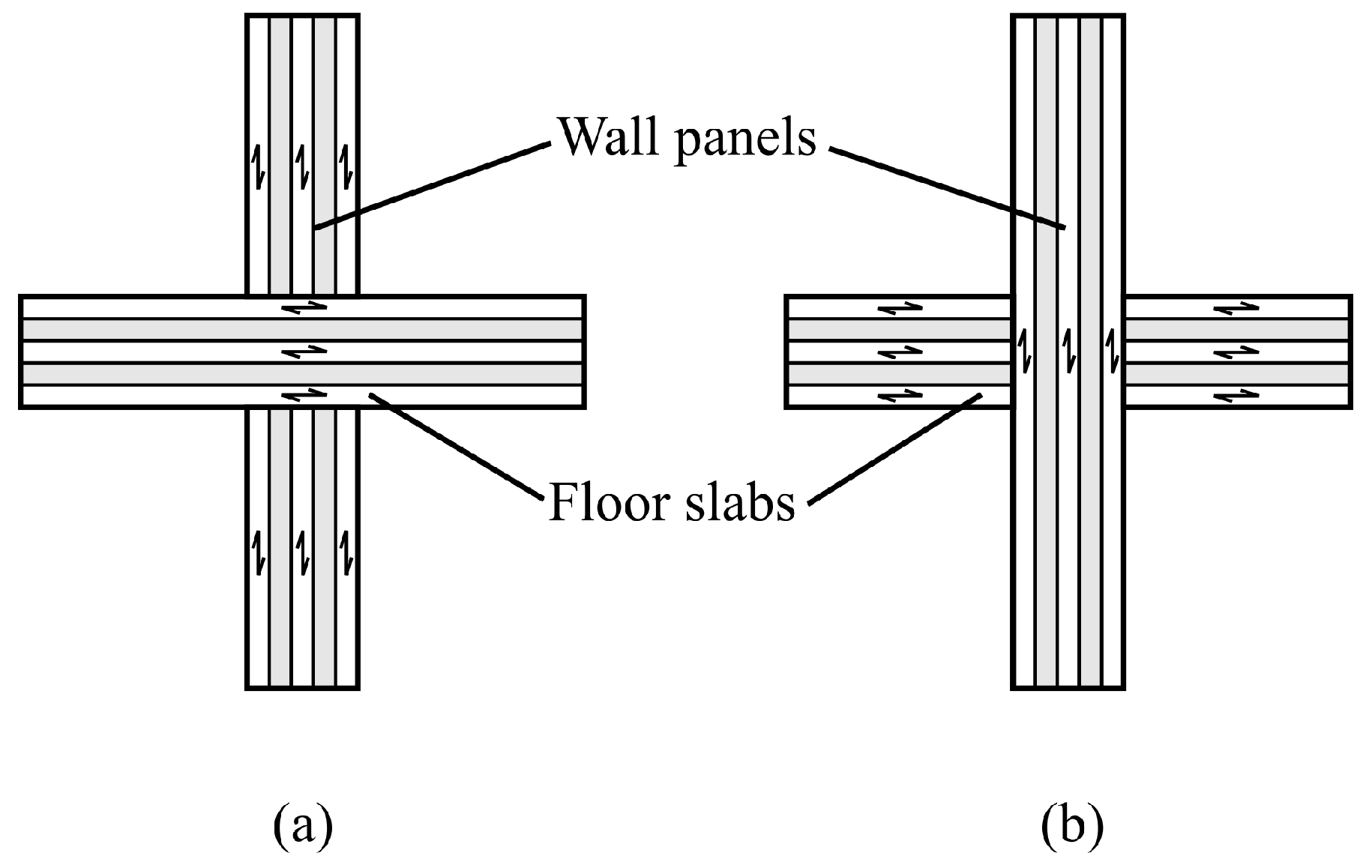
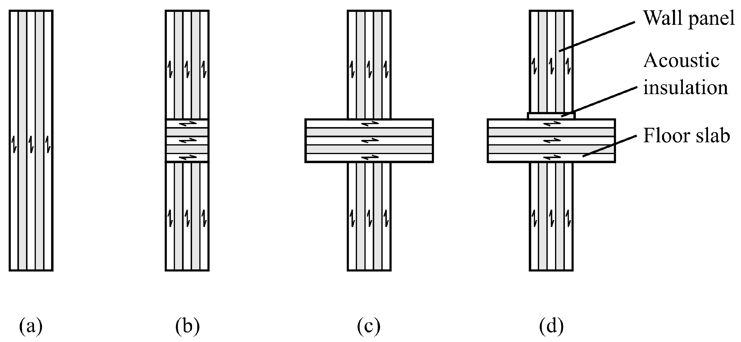
Due to its fibrous structure, timber exhibits anisotropic stiffness properties, with significantly higher stiffness along the direction of the fibres. The material properties are commonly assumed to be transversely orthotropic. Despite the pronounced disparity in stiffness between the radial and the tangential directions, engineering applications often assume equal properties in these two directions. This assumption is primarily rooted in the considerably higher stiffness along the grain. For Norway spruce, the stiffness in the radial direction is approximately 1.5 times higher than in the tangential direction [19], while the stiffness along the grain is 20 to 30 times higher [19]. Depending on the installation of the floor slabs, a distinction is made between the platform frame and the balloon frame types of construction (see Figure 1). The difference between the along-the-grain and the perpendicular-to-the-grain material properties becomes an important factor in the platform frame CLT buildings, where floor slabs are compressed in the perpendicular-to-the-grain fashion. Due to the lower strength, inelastic deformation perpendicular to the grain is observed under high vertical loads [27]. While such loads do not lead to structural failure [24], they may cause deformations significant enough to damage non-structural elements such as plasterboard or façade. Considering the stiffness of the building in the vertical direction, floor slabs have a substantial impact despite their small thickness compared to the height of the walls. To illustrate this, four cases are presented in Figure 2. In case (b), inserting a perpendicularly oriented interlayer between two walls reduces the overall vertical stiffness compared to case (a). A simple example [28] demonstrated up to 50% reduction, assuming the commonly used dimensions for slab thickness and wall height. When the floor slab width exceeds the wall thickness, as in case (c), the overall vertical stiffness increases due to the stress dispersion under the wall [29]. Stress dispersion angles of 45° and 15° in the direction parallel and perpendicular to the grain, respectively, were proposed [24]. Conversely, a significant decrease in stiffness was observed after the installation of a layer of vibroacoustic insulation under the walls [29], as illustrated in case (d). Similarly, it was observed that a layer of vibroacoustic insulation decreases the stiffness in shear testing as well [30].
Another important decision is how to model connections between the panels. In the presence of seismic actions, the dynamic behaviour of a building is largely influenced by these connections. Namely, to avoid a brittle failure, the CLT members are overdesigned compared to the strength of the connections [31]. With the aim to better understand the performance of the connections when subjected to seismic actions, monotonic and cyclic tests were carried out on hold-downs and angle brackets [32,33], screwed lap joints [34,35], and wall systems [36]. When subjected to shear loading, CLT walls typically exhibit three types of deformation mechanisms: rocking, sliding, and in-plane deformations of the panel. A monotonic test on the CLT wall connected to the CLT floor with angle brackets showed that only from 20% to 35% of a lateral displacement at the failure was attributed to the in-plane deformation of the panel [27]. However, at smaller displacements, the contribution of the panel deformation was higher. For example, at yield displacement, the in-plane deformation of the panel accounted for up to 56% of the lateral displacement. Contributions of different deformation mechanisms were not analysed for smaller amplitudes, so the results cannot be extended to small amplitude vibration (such as is expected from wind loading). Rocking is a leading failure mechanism in monotonic tests, especially for the CLT panels with a small width-to-height ratio [27]. Nevertheless, when vertical loading is considered, the rocking of the CLT panels occurs only after a certain threshold lateral load [37]. Shaker dynamic testing and quick-release testing of a CLT and timber frame structure revealed amplitude dependency of the stiffness of the structure. When the rocking of the CLT panel is activated, the stiffness and the fundamental natural frequency drop significantly [37]. It is not yet known whether the wind-induced vibrations exceed the activation level of the rocking mechanism.
The models for predicting modal properties of timber buildings are uncertain due to the presented underlying reasons connected to the varied material properties, joints, and connections between timber members, and the effects of non-structural elements. Despite the importance of vibration serviceability for timber buildings, there is a lack of comprehensive research. The investigation presented in this paper is focused on assessing the accuracy of the FE models based on the modal testing results, and it improves them by employing advanced model updating techniques. The aim is to identify the important effects that need to be taken into account for the accurate modelling of timber buildings.
The rest of this paper is organised in the following way. Section 2 provides an overview of the relevant literature related to modal testing, modelling, and model updating of timber buildings. In Section 3, the methodology for the FE modelling and model updating of CLT buildings is introduced. Case studies of three CLT buildings are briefly presented in Section 4, describing the buildings and their initial and updated FE models, together with the serviceability verification. In Section 5, the results of the case studies are reported and followed by a discussion in Section 6. Finally, conclusions are drawn in Section 7.
2. Modal Testing and Model Updating
Numerical models can be improved using the data from experimental tests with a procedure called model updating. The research into model updating had already started in the 1970s; however, the process was defined more formally in the 1990s [38,39]. Since then, model updating has not only become a broad scientific topic [40] but has also developed into mature technology applied in various industries [41]. As a scientific subfield, structural health monitoring [42,43] employs model updating for damage detection, which is also used in civil engineering applications [44]. For example, model updating was applied to bridges [45,46,47], as well as a super tall building [48] and historical buildings [49].
One of the advanced techniques is probabilistic model updating, which is based on the Bayesian inversion. By taking uncertainties and errors into account, the end result is not a point estimate that minimises the objective function, as is the case with classical model updating, but rather an updated probability distribution of the parameters. Such a probabilistic framework offers a comprehensive solution that not only allows for the derivation of a singular point estimate but also provides a confidence interval for the results [50]. Some examples of applications in civil engineering are given in [51,52]. Bayesian model updating is often performed by stochastic methods. One such method is Markov chain Monte Carlo (MCMC), which is an iterative sampling procedure to find the Bayesian posterior distribution of the model parameters in the form of samples. Each iteration involves running an FE model with different values of the modelling parameters, leading to a high computational burden, especially for complex (i.e., with a high-degree-of-freedom) FE models. An improvement in computation time can be achieved by using a surrogate model that approximates the solution of the FE model analysis. An approach that is well suited to the probabilistic framework of the Bayesian updating is the generalised polynomial chaos expansion (gPCE), which approximates the probabilistic output of the model with the help of a special set of polynomials that are orthogonal with respect to the underlying prior probability measure. The polynomial chaos expansion was first introduced in [53] to describe stochastic processes with Gaussian random variables with the help of Hermite polynomials. The description was generalised in [54] to variables with other distributions in the form of what is called generalised polynomial chaos expansion.
In general, experimental data used for model updating are any measured quantity that can be quantifiably compared to the numerical model. For civil engineering applications, it is modal properties that are most often used for comparison. However, other static or dynamic quantities of interest can be used as well (such as deflections, strains, frequency response functions, etc.). The vast majority of the published literature uses ambient vibration testing (AVT) to experimentally estimate the natural frequencies, mode shapes, and modal damping ratios. Due to the low energy of excitation (usually wind loading), the number of modes measured with AVT is low, compared to the forced vibration testing (FVT), where the building is usually excited by a shaker [55]. Higher quality data are usually expected with FVT, as the inputs are controlled. However, due to technical challenges, AVT is often the first choice for obtaining experimental data.
Over two decades ago, Ellis and Bougard [56] conducted tests on a six-storey light-timber-framed building in a laboratory setting. The building consisted not only of a load-bearing structure but also featured brick wall cladding, plasterboards, a staircase, and roof tiles. They performed AVT and FVT testing in several construction phases. The study showed a significant increase in the fundamental frequency after installing plasterboards and a staircase, as well as an additional increase after masonry cladding was constructed. Despite important findings, the study lacked FE modelling and the building featured a standard timber rather than CLT.
A study by Steiger et al. [57] was conducted on a three-storey light-frame timber building sheathed with oriented strand boards (OSB) featuring timber–concrete composite slabs. This study also observed a significant increase in natural frequencies after the installation of the non-structural elements. Testing the building with AVT and FVT at varying amplitudes revealed that the stiffening impact of non-structural elements diminished with higher vibration amplitudes. Conversely, damping increases with a higher vibration amplitude.
Reynolds et al. [58] measured a seven-storey CLT building with AVT in two construction phases. Contrary to the previous findings, this study showed a decrease in natural frequencies after the installation of non-structural elements. In addition to installing plasterboards and cladding, the second phase featured an additional layer of screed, which largely contributed to the total mass of the building. Similarly to other studies, the installation of non-structural elements significantly increased the damping.
A set of seven CLT buildings ranging from 9 to 13 storeys were tested with AVT by Tulebekova et al. [59]. The buildings were modelled with full-scale FE models, exhibiting natural frequencies that are 10% to 20% lower than what was measured. The updating of the model identified a softening effect of the connections, both axially and shear. It should be noted that all of those platform-frame buildings featured vibroacoustic insulation under the CLT walls, which can reduce the stiffness by as much as 60% [30].
Larsson et al. [60] analysed a 9-storey CLT building during the 13-month construction, performing AVT in seven different construction phases. They observed an increase in natural frequencies after installing non-structural elements (such as a façade and plasterboards). The building was modelled in all seven measured states of construction; the natural frequencies were significantly higher than those obtained from measurements. Again, the vibroacoustic insulation was installed under the CLT walls, potentially reducing the stiffness of the building.
The referenced case studies converge on the conclusion that non-structural elements, such as facades and plasterboard, contribute to an increase in natural frequencies. The one exception [58] that showed a decrease in natural frequencies combined the effect of adding, not only plasterboards and façade cladding, but also screed, which significantly increased the mass of the building. A similar effect of non-structural elements that increase natural frequencies can be found for classical reinforced concrete and steel structures [61,62,63].
It should be emphasised that natural frequencies of timber buildings are subject to a significant seasonal variation, due to changes in the moisture content. The three-year monitoring of a four-storey hybrid timber–concrete building was conducted by Larsson et al. [64]. A 10% variation in the fundamental natural frequency was observed, with the higher moisture content yielding stiffening and a higher natural frequency.
Many more timber buildings have been examined. Leyder et al. [65] tested the top two timber storeys of a four-storey building. It consisted of a post-tensioned timber frame and timber–concrete composite floor. Mugabo et al. [66] tested a four-storey building with a GLT framing system and CLT floors. Reynolds et al. [67] examined two five-storey timber buildings with a concrete core. The two buildings were identical except for their structural system, one featuring an OSB sheathed light timber frame; the other was a CLT building. Tulebekova et al. [68] tested Mjøstårnet, currently the highest timber building in the world, with the main structural system consisting of a GLT frame, but featuring also CLT and laminated-veneer lumber (LVL). Aloisio et al. [69] reported results of AVT conducted on an eight-storey CLT building. Several more studies were gathered in a state-of-the-art review by Aloisio et al. [70].
From the above, it can be concluded that the majority of the research, related to the investigation of dynamic properties of existing tall timber buildings, focused primarily on measuring modal properties, and only some studies were also accompanied by FE models of various complexity. In general, the research field lacks guidelines for the creation of (refined and accurate) FE models of tall timber buildings, which should serve for checking the vibration serviceability criteria. The basis for such guidelines may be achieved by a comprehensive structural identification of a set of existing tall timber buildings. This would enable an estimation of the nature and the level of importance of various effects (related to different building components) on the dynamic properties of timber buildings. This study reports on these effects for three CLT case studies.
To the best of the authors’ knowledge, the Bayesian finite element model updating has not been applied for timber buildings, except for the cases presented in this work. Furthermore, it seems that this work is the first attempt to identify the common features of the findings obtained by updating the models of several timber buildings of the same type.
3. Materials and Methods
Although the models that can accurately predict modal properties are needed, a balanced trade-off between accuracy and simplicity is still desired. To that end, modelling assumptions that were taken into account in the present work are the following:
- Geometry of the building is modelled in detail, including the openings in the walls. Only the small holes for ventilation, heating, plumbing, and electric installation are neglected (of an area smaller than approximately 0.2 ).
- Wall and floor CLT panels are modelled by shell finite elements with transversely orthotropic layers.
- For the transversely orthotropic material model, mean material properties from ETAs are used.
- The CLT panels are assumed to be rigidly connected with each other, i.e., connections between the CLT panels are not modelled explicitly.
- The soil stiffness is modelled either by a set of discrete elastic springs or by an area-distributed elastic support in the vertical direction.
- The mass of non-structural elements was uniformly distributed over the CLT panels on which they are attached (i.e., it was distributed over either walls or floor slabs).
Constructing an FE model involves assembling a stiffness matrix and mass matrix . An undamped modal analysis consists of solving a system of differential equations of the form
which translates into identifying pairs of eigenfrequencies and eigenvectors that satisfy the eigenvalue problem (e.g., [71])
The set of modal properties obtained by the FE model is denoted by for the eigenfrequency and by for the eigenvector of mode r.
The next step is to perform modal testing and thus to obtain a set of experimental modal properties. Let denote the eigenfrequency and the eigenvector of mode q. Due to the non-proportional damping of real structures, the modal identification typically results in a complex eigensolution. Sometimes it is useful to realise eigenvectors, especially for the visualisation and comparison of the modes. Ahmadian [72] showed that the realised eigenvector that correlates most with the original complex eigenvector is obtained by taking the real part of an eigenvector that is rotated in the complex plane
for such angle that
The correlation between the experimental and the FE eigenvectors can be quantified using the modal assurance criterion (MAC), e.g., [73,74]. It may take complex eigenvectors and is calculated as
where and are a pair of eigenvectors to be compared and ∗ denotes the conjugation of a complex eigenvector. A MAC value of 1 suggests a perfect correlation between the 2 eigenvectors, whereas a value of 0 suggests no similarity [74].
The model can be improved based on a measure of correlation with the experiments. The model updating can be carried out. Two distinct approaches are available: the deterministic and the probabilistic approach. The deterministic approach is a classical optimisation problem (e.g., [75,76,77]), and can be described as
where an objective function J is minimised by changing parameters of the model while respecting constraints and . The objective function is formulated in a way that captures a distance between the model results and the experimental data . Typically, some constraints define the upper and the lower bounds of parameter values, and others restrict some model results to certain values. Applying Equation (7) changes the model so that it provides results that are very close to the experimental data. When modal properties are considered as a measure of correlations, a possible objective function can be defined by the weighted mean squared differences
where and are the weights of the two measures of distance, and is the MAC value of the r-th pair of the correlated modes. The objective function may be of a different form or there may even be multiple objective functions. Once the problem is formulated this way, a wide array of classical optimisation methods is available (e.g., a gradient method, particle swarm optimisation, and genetic algorithm) to find a minimum of J.
In contrast to classical optimisation approaches, the probabilistic approach does not seek to identify an optimal set of parameters, which is often just a local minimum. Instead, it assesses the probability distribution of parameters taking specific values. This methodology relies on Bayes’ theorem (e.g., [50,78]), expressed as
where prior encapsulates the initial knowledge about parameter values reflecting the engineer’s uncertainty in the values of the modelling parameters and the corresponding probabilities based on engineering judgement.
The likelihood incorporates experimental knowledge by evaluating how likely is it to measure the experimental modal properties given a certain “true” value of the parameter .
The likelihood incorporates experimental knowledge by evaluating how likely is it to measure the experimental modal properties , given a certain “true” value of parameter . The likelihood is computed from the probability distribution of the measurement error, a function of the distance between the measured modal properties , and the modal properties computed by the model . The evidence is a normalizing constant, which ensures that the integral of the posterior distribution over the parameter space equals 1. Estimating the posterior distribution using a sampling technique such as the Metropolis–Hastings algorithm (e.g., [79]) avoids calculating the evidence, as it cancels out in the process.
4. Case Studies
The case studies pertain to three timber buildings, each entailing the measurement of the modal properties, the prediction of the modal properties using the FE software ANSYS, and the subsequent model updating. The process of model updating and the associated analyses differed across the case studies, with each case presenting its own challenges.
4.1. Model Updating of a Seven-Storey CLT Building
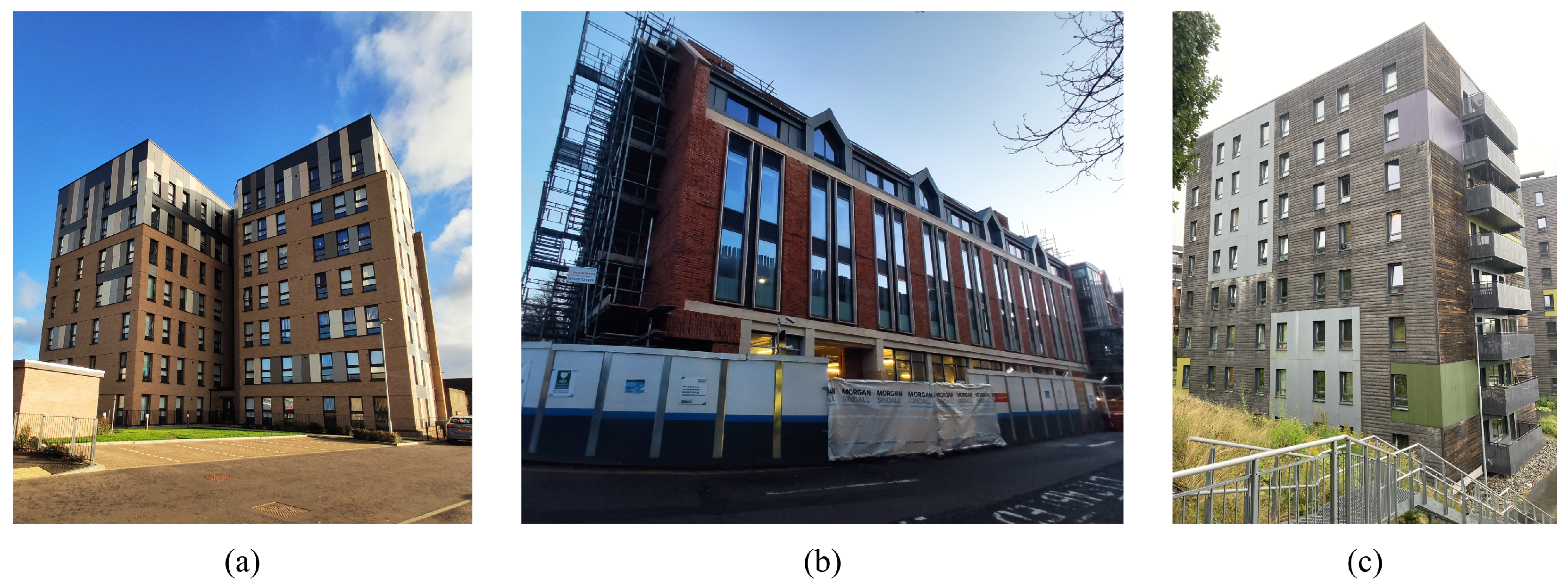
The observed building is a seven-storey CLT building, located in Glasgow, Scotland (see Figure 3a). It has an irregular T-shape with gross plan dimensions of and a height of 22 m. The load-bearing structure is of a platform frame type, and it features large monolithic CLT panels. The façade consists of a thin cladding imitating a masonry wall on timber battens. The internal walls are covered by plasterboards, and the building also features some partition walls. No vibroacoustic insulation is installed under CLT walls. A layer of screed is an important contribution to the total mass of the building.
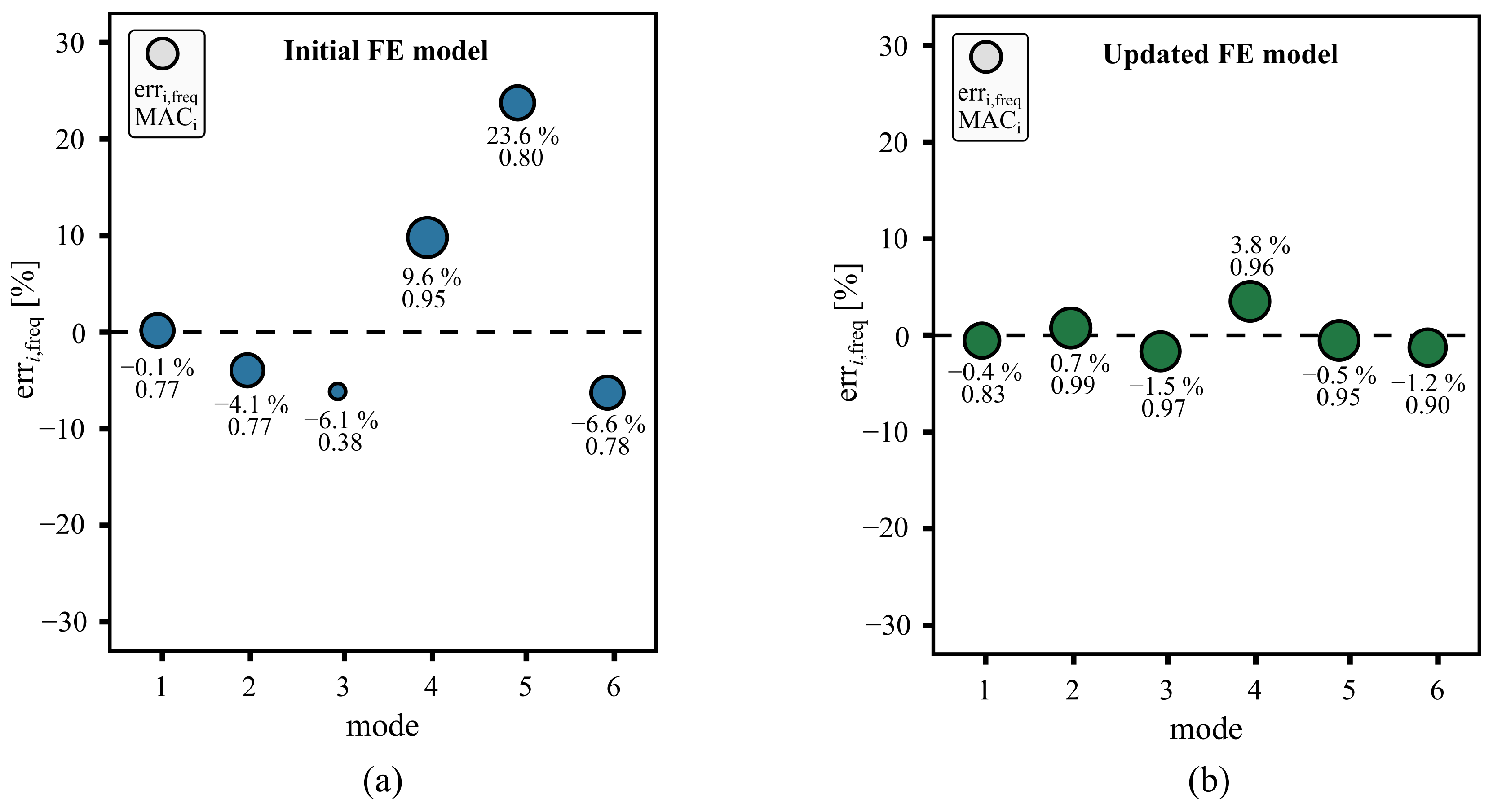
An FRF-based modal testing [80] was performed by exciting the building with a shaker positioned on the 6th floor. Accelerations were measured at 13 sensor locations throughout the height of the building. Due to the inaccessibility of the apartments for the measurements, the sensors were placed in the corridor in the centre of the building, which resulted in spatial aliasing [81]. A single-input and multiple-output modal identification (complex mode indicator function) was used to identify eight modes of vibration. Of those, six could be matched with the FE model. However, the initial model was very poorly correlated, especially the mode shapes, for which the MAC values were as low as 0.4 for the third mode. The FMAC plot [82] in Figure 4a shows the matching of the initial FE model with the measured modal properties.
To improve the initial model, the updating of six parameters was performed. The objective function in the deterministic model updating combines the relative difference of experimental and numerical natural frequencies and the MAC values for a measure of the mode shape correlation. The updated model shows a vastly improved correlation with the measured modal properties, which is shown in Figure 4b. The building, experimental setup, modal identification, modelling, and model updating are presented in more detail in [28].
Additionally, the probabilistic model updating was carried out. It resulted in similar conclusions regarding the most likely updated values. Furthermore, it offered a better insight into the underlying uncertainties connected to the updated values. The Bayesian inference was performed by the MCMC sampling of the posterior distribution. Uninformative prior distributions were adopted for the input parameters, and the likelihood function was constructed based on the uncertainties of the experimentally obtained modal properties. For the computational efficiency of stochastic analyses, a gPCE surrogate model approximating eigenfrequencies and eigenvectors was developed. The main challenge in constructing a surrogate model was the changing mode order, which was solved by k-means clustering of the mode shapes. For details about the probabilistic framework and the results of the probabilistic model updating, see [83].
4.2. Model Updating of a Five-Storey Hybrid Timber–Concrete Building
Secondly, a five-storey hybrid timber–concrete building in Cambridge, UK (see Figure 3b), was studied. The basement and ground floor are made of reinforced concrete; the remaining four storeys are from CLT. The prevalent type of construction is the platform frame; see Figure 1a. However, at certain locations, the wall continuity is applied at the floor level, which avoids the transfer of vertical loads across the thickness of the floor slab. At these locations, the floor slab is laterally connected to the wall, as in Figure 1b. The building also features one panel of the lift shaft spanning over the top four storeys. No vibroacoustic insulation is installed under any of the CLT walls. The building has a gross plan, and the overall height is 16 m. The external walls are made of monolithic CLT panels with a large length-to-width ratio. The façade is made of a self-supported masonry wall that is connected to the CLT load-bearing structure by horizontal ties. The majority of the mass comes from the two concrete storeys, the masonry façade, and the screed installed on top of each floor slab. Their stiffness effects are explored together with the effects of non-structural elements (such as plasterboards, partition walls, and a roof) with model updating. To the already high complexity of structural systems of the building, an uncertainty of the effect of the adjacent abutting building is added. Even though the buildings are designed as structurally independent, they share a foundation and are in contact over one wall.
FRF-based modal testing was conducted on the building, with excitation applied using a mass shaker situated on the third floor. A better placement for the shaker would be on the top floor, which was, however, inaccessible during the measurements. Accelerations were measured in the 11 sensor locations, each equipped with two orthogonally oriented accelerometers. The multiple-input and multiple-output modal identification successfully captured three vibration modes. Although higher modes were observed, they could not be reliably identified, probably due to the non-linearity of the contact with the adjacent building. The mode shapes computed by the FE model exhibited a poor correlation with the experiments. Notably, the MAC value of the first mode was lower than 0.5. The FMAC plot in Figure 5a shows a matching of the initial FE model with measured modal properties.
In this case study, only deterministic model updating was conducted, but the underlying uncertainty was considered in a different way. The objective function included a measure for natural frequency and mode shape matching with the experiments. Several iterations were repeated with different sets of updating parameters, which resulted in a higher confidence in the results and an estimation of the uncertainty for the updated parameter values. Altogether, six parameters were explored, three of which were observed to be the most important for improving the model. The matching of the updated model with the experiments is shown in Figure 5b. The procedure is explained in more detail in [84].
4.3. Model Updating of an Eight-Storey CLT Building
The third studied building was an eight-storey CLT building, located in Ås, Norway (see Figure 3c). Large monolithic CLT panels are assembled in a platform frame type. It has a rectangular shape of , which are the gross dimensions in the plan, and a height of 27 m. The design of the building is very lightweight with thin wood cladding and no screed, with some CLT walls being exposed. Other walls are covered with plasterboards. A large contribution to the total mass is due to the bathroom pods—prefabricated modules that are installed on the load-bearing structure without any strength and stiffness contribution per design; however, its as-built contribution is unknown.
In contrast with the previous case studies, only AVT measurements could be performed on this building. Accelerations were measured at three sensor locations on the roof, each measuring in two horizontal directions. Two 90 min signals were obtained and used to identify four modes of vibration. The SSIcov modal identification was used. Figure 6a shows a good matching of mode shapes of the initial model, while natural frequencies deviate from the measurements up to 15%. A probabilistic model updating was performed to improve the knowledge of five input parameters, for which an uninformative prior was adopted. The likelihood function assumed a normally distributed unbiased error of natural frequencies. Its variances were estimated by splitting the measured signal and carrying out modal identification on the split intervals. A surrogate model for eigenfrequencies was developed with the gPCE to improve the computational efficiency of stochastic analyses. Details about the building, measurements, FE modelling, and model updating are provided in [85].
4.4. Serviceability Check
For all three case studies, peak accelerations were verified according to Annex B of Eurocode 1 and ISO 10137. Parameters used in the calculations, according to Eurocode 1, are shown in Table 1. The values for the basic wind velocity are taken from the respective national annexes. For the calculations, the first two bending modes were considered in all three case studies. The natural frequencies were obtained from the experiments. The value for damping was assumed based on the reports in the literature. For example, damping ratios in some of the observed timber buildings [59,68,69,80], were identified to be between 1.2% and 2.3%, and, most commonly, between 1.5% and 2.0%. For hybrid timber buildings, damping ratios were identified to be higher—between 1.5% and 3.0% [64], or even as high as 4.0% [84]. In the case of long-term monitoring [64], a large variance was observed for the identified damping ratio. Moreover, it may even be amplitude-dependent [86]. To that end, the damping ratio was conservatively assumed to be 1.2%. Calculations according to EC 1991-1-4 assume damping in the form of the logarithmic decrement , which is connected to the damping ratio , as
The computed values of peak accelerations are compared to the maximum allowed peak acceleration of ISO 10137; see Figure 7. The first case study just barely exceeds the limit curve for residential buildings. For a higher value of the assumed damping ratio, the design could satisfy the criteria of ISO 10137. The second case study is well below the curve due to the lower height and higher mass. Interestingly, the second mode seems to have significantly higher peak acceleration values. Finally, the calculated peak accelerations of the third case study significantly exceed the proposed maximal values for the first mode.
5. Results
Finding the right parameters for model updating requires some level of investigation work. The unique challenges of the three case studies led to the selection of different parameter sets, consisting of three to six parameters. Generally, the more the measured modes of vibration are included in the objective function (or the likelihood, in the case of the probabilistic framework), the more parameters can be updated. Even though the parameter sets were unique for each case study, some general trends can be observed. The two trends that were the most pronounced are presented in this section. The parameters included in their modelling were defined differently from case study to case study; however, they were slightly adjusted for presentation purposes. The case studies should be consulted for their exact definitions [28,84,85].
The first trend observed is that the shear stiffness of the walls is higher than anticipated by the initial models. These models neglected the influence of non-structural elements attached to the walls (such as façade, plasterboard, and partition walls) and used the in-plane shear modulus stated by the manufacturers in their ETAs. The cause for the discrepancy between the updated and the initial models may stem from the material properties of the CLT walls and/or the influence of the non-structural elements, encapsulated by the scaling parameter . This parameter, which was defined to multiply the mean in-plane shear modulus of CLT from the manufacturer’s ETA , yields the corrected in-plane shear modulus of the walls
accounting for the effects of non-structural elements and the shear compliance of wall–floor connections, as well as the conservatively estimated shear modulus of the CLT panels. The updated parameter values of the three case studies are shown in Table 2, together with the impact of the updated parameter value on the natural frequencies. The impact of the parameter is computed as a relative change of the natural frequencies when the parameter is changed from the initial value to the updated value, while the remaining parameters take the updated value. It can be observed that the fundamental frequency is underestimated by roughly 10% to 20%, when non-structural elements are neglected. The effects on the second and third natural frequencies are similar. The updated values of are shown in Figure 8, where they are compared to the values of the in-plane shear moduli stated by the manufacturers of the CLT panels in their ETAs. The values of 650 MPa and 450 MPa that are proposed by Brandner et al. [23] for the CLT, with or without the narrow edge bonding, respectively, are added to the plot as a reference. The procedure for obtaining the updated values and respective confidence intervals varied between the case studies. In the first and the third case studies, probabilistic model udpating was used. The updated values refer to the estimate of the maximum a posteriori, and the confidence intervals were obtained by taking the 5th and the 95th percentiles of the posterior distribution. In the third case study, the stiffness of the external and internal walls were separated into two parameters. The parameter corresponding to the external walls (on the right) resulted in approximately 20% higher values. The second case study was based on the deterministic model updating. Several iterations were repeated while changing the modelling assumptions. The confidence interval reflected the uncertainty of the model by changing the assumed mass of the building between 80% and 110% of the initial estimate. The updated value refers to the solution of the iteration with the initial building mass estimate. Details of the procedure are described in [84].
The second trend that is evident is the lower vertical stiffness. The two main contributors are the foundation and the elastic modulus of vertical layers of the walls, which are defined by parameters and , respectively. They have a similar influence on the modal properties of the building; thus, the model updating may have difficulty distinguishing between the two. The more the measured modes of vibration are available, the higher the chances of successfully distinguishing between these two parameters. For example, case study 3 showed that only after introducing the fourth mode of vibration to the likelihood, the two parameters were able to be distinguished by the model updating procedure.
Parameter models the vertical stiffness of the foundation. In case study 1, piles are modelled with discrete springs, where the denotes the vertical stiffness of one pile. In case studies 2 and 3, the foundation is modelled with elastic support, where denotes the distributed spring stiffness in the vertical direction. The updated values are presented in Table 3, together with the impact on the first three natural frequencies. It can be observed that the soil deformability in case studies 1 and 2 reduces natural frequencies compared to the rigid boundary condition by up to 20%. On the other hand, case study 3 shows that the assumption of a rigid foundation was suitable.
Parameter models the effect of the wall–floor–wall joint in platform frame buildings, where the perpendicular-to-the-grain stiffness of floor slabs plays an important role. It is implemented so that the along-the-grain elastic modulus of vertical wall layers is computed as
where denotes the mean along-the-grain elastic modulus of timber proposed by the CLT manufacturers in their ETAs. The updated values and their impact on the natural frequencies are presented in Table 4. Case study 2 did not include this parameter in model updating due to the relatively small sensitivity of modal properties to this parameter. For case studies 1 and 3, it can be observed that the fundamental frequency is overestimated by roughly 6% to 8% when the effect of the wall–floor–wall joint is neglected.
6. Discussion
The updated values presented in the previous section should not be directly generalized to the models of other buildings. They reflect the designs of particular buildings, which may have different structural solutions. For this reason, the presented results are put in the context of individual case studies. The description of their respective structural systems may provide an explanation of the updated parameter values. This can help modellers consider the important effects and understand their uncertainties.
6.1. Features of Used FE Models
The basic features of the used FE models may be summarised as follows:
- All load-bearing walls were considered in the model.
- Only a small percentage of the (non-load bearing) partition walls were not included in the model.
- The floors were modelled as deformable, i.e., an assumption of rigid diaphragms was not applied.
- The soil deformability was taken into account by springs.
- The dead mass of the building was carefully estimated from the design documents.
- A fine mesh of shell FEs with transversely orthotropic layers was used, making the discretization error small.
- Connections between CLT panels were not modelled explicitly.
The latter point might be considered a disadvantage of the used FE models, although it is not yet clear whether the explicit modelling of connections provides any advantages for the analysis of vibration serviceability.
6.2. Façade and Other Non-Structural Elements
Case study 1 resulted in an updated value of the in-plane shear stiffness of the CLT walls that was 63% higher than in the initial model. A thin cladding imitating masonry wall—acrylic brick slip—on timber battens (all together, approximately 5 cm thick) is used as a façade system. Together with plasterboards and partition walls, they might contribute to the significantly higher updated value. It is also possible that the stiffness of the CLT alone is actually higher. Based on the observations of Brandner et al. [23] for panels with narrow sides of lamellae glued together, this amounts to a shear modulus of up to 650 MPa. After inquiry, the manufacturers of the CLT panels stated that narrow sides are glued together, but only for the ease of assembling in the manufacturing process. They do not perform any quality control on these glued joints and thus the performance is not guaranteed (which is reflected by not as high value in the ETA). Since the measurements were carried out two years after the completion of the construction, some cracks in the glued joints or the CLT panels might have already started to appear.
In contrast, the façade system in case study 2 is much stiffer. It consists of 100 mm thick masonry cladding, which is a self-supported masonry wall. It is connected to the CLT walls with horizontal ties that allow for a vertical differential movement. The study showed that the masonry façade had to be modelled. Even when it was modelled as a rigidly bonded layer to the CLT, the in-plane shear modulus of the CLT walls was updated from 25% to 110%, which was a higher value than the one provided by the manufacturer (500 MPa). When the masonry façade was neglected, the model updating resulted in almost four times the value. The measurements on this building were carried out just before the completion of the construction; thus, the state of the panels was likely to be very good (with cracks not appearing yet).
Finally, the façade of case study 3 consisted of 2 cm thick timber cladding on timber battens, which was connected to the CLT panels. Due to the simplistic design (not only because of the thin façade but also because of many exposed internal CLT walls), it can be expected that the contribution of non-structural elements should not be high. The available documentation of the manufacturer (i.e., ETA) proposed 250 MPa for the in-plane shear modulus. The model updating suggested that the most probable value was between 400 MPa and 450 MPa for internal walls and roughly 20% higher for external walls. The measurements were carried out 10 years after the completed construction. During this time it is likely that cracks have appeared, causing the stiffness of the panels to reduce. Another difference between this building and those of case studies 1 and 2 is that it featured vibroacoustic insulation under the internal walls, which very likely reduces the stiffness of the building [30]. A large standard deviation of the updated values of the shear modulus makes it difficult to draw clear conclusions in this case study.
6.3. Connections
Steel connections were not modelled explicitly. In all three case studies, panels were modelled as rigidly connected. However, the effect of steel connections was not overlooked. It was assumed that the potentially lower stiffness of the building due to the connection compliance would result in lower values of the updated in-plane shear modulus and thus the effect could be discerned indirectly. Generally, higher updated values of the in-plane shear moduli suggest that the connections do not significantly reduce the overall stiffness of the building.
With only three case studies, this conclusion should not be generalized. A different conclusion about the stiffness of wall–floor connections was, for example, reached by Tulebekova et al. [59]. In the model updating of two CLT buildings, they found that the shear stiffness of the connections should be modelled. The discrepancy between these contrasting conclusions could be attributed to the fact that these two observed buildings featured a layer of vibroacoustic insulation under the CLT walls, while the three buildings presented in this paper did not. As pointed out by Azinović et al. [30], such a layer may have a significant effect on the shear behaviour of the CLT wall systems.
In contrast with the findings of this paper, the seismic analysis is based on the expectation that connections govern the dynamic behaviour of the building, since the CLT members are overdesigned to avoid brittle failure [31]. However, it should be pointed out that in extreme load cases, the static friction force is exceeded, and the rocking of the panels is expected. On the other hand, when the building is exposed to low amplitude loads (for example, due to the wind), the friction force might not be exceeded and the connections are not engaged. It was shown by Casagrande et al. [37] that at a certain threshold of the load amplitude, panels started to rock, leading to an evident reduction in the natural frequency.
A distinction should also be made between different types of connections. For example, in some joints, the static friction force is high due to high vertical loads (such as wall–floor–wall joints in platform frame buildings). On the other hand, in joints where the static friction force is low (such as the in-plane panel connection-nailed lap joint or the connection with a steel plate), the stiffness of such connections could play an important role. In all three observed buildings, walls were made from large monolithic panels rather than segmented ones. Thus, no information on the in-plane wall–wall connection was acquired within any of the three case studies.
6.4. Foundations
The soil deformability is another contributor to the modal properties and is very unique for each building. As the main boundary condition, it can very markedly influence the modal properties of the building. In case study 1, where the building is constructed on soft clay and supported by piles, the model updating suggested that a slight vertical softening of the boundary condition (compared to the assumption of a rigid foundation) improves the agreement with the experiments. However, the elastic modulus of vertical layers and vertical foundation stiffness affect the model very similarly and could not be definitely pinpointed to the correct contributor. In case study 2, the foundation proved to be one of the two most important parameters for improving the model. The soil beneath the building consists of dense gravel and stiff clay. Finally, the model updating of case study 3 showed that the foundation should be modelled as rigid. This was found when four modes of the vibration were included in the model updating. In the case of updating with only three modes, the effects of the elastic modulus of vertical layers and the vertical foundation stiffness could not be distinguished.
7. Conclusions
Based on the structural identification of two CLT and one hybrid CLT–concrete buildings (between five and eight storeys high), the following findings about the FE modelling of CLT buildings for vibration serviceability were obtained:
- The initial (i.e., the best-engineering-judgement) FE models that were prepared by the careful meshing of the geometry of the buildings with layered shell finite elements estimate the fundamental natural frequencies reasonably well (with relative errors up to 10%). They assume rigid connections between the CLT panels, fixed supports at the level of the foundation, and neglect the non-structural elements (such as plasterboards and thin facades).
- The model updating showed that different modelling errors are present in the initial FE models and that their effects are cancelling out. Therefore, a good prediction of the natural frequencies by the initial FE models is a fortunate coincidence.
- The model updating showed that the main sources of the modelling error are the shear stiffness of the CLT walls, the soil deformability, and the perpendicular-to-the-grain deformations of the floor slabs.
- By neglecting the non-structural elements and by using the in-plane shear modulus from the manufacturer’s ETA, the shear stiffness of the walls is largely underestimated.
- The foundation and soil modelling may significantly reduce the stiffness of the building, causing the natural frequencies to drop by up to 20% compared to the assumption of fixed supports. Similarly, the perpendicular-to-the-grain deformations of floor slabs may also reduce the stiffness of the building, corresponding to a drop in the natural frequencies by up to 8%.
- Modelling the wall–floor connections as rigid turned out to be suitable for the observed case studies. However, in some cases (especially when a vibroacoustic insulation layer is added under the CLT walls), this assumption may not be appropriate.
Furthermore, the following can be concluded about the model updating based on modal testing for CLT buildings:
- The success of the procedure depends on the number of parameters that may be identified, which is limited mainly by the amount and quality of the experimental data. These may be improved by using FVT instead of AVT. The description of the process of selection of the parameters for the model updating is omitted here for the sake of clarity, but it is presented in detail in accompanying papers [28,84,85].
- The model updating is governed by the likelihood function (or by the objective function in the case of the deterministic model updating). In the present work, the likelihood and objective function use fundamental natural frequencies and the mode shapes (from three to six), and the results improve by increasing the number of eigenfrequencies [84].
- The consequence of such model updating is that the updated model has an excellent predictive power for the dynamics predominated by the fundamental vibration modes. It is very likely that the updated model has a better accuracy prediction also for the higher vibration modes (that was studied and confirmed for the first case study). It can be noted that in the case of wind-induced vibrations, the fundamental modes (usually up to the third one) are of a key interest.
- The application of the probabilistic framework for the model updating avoids drawing overconfident conclusions.
Author Contributions
Conceptualization and Methodology, B.K., N.F. and B.B.; Software and Validation, B.K. and N.F.; Investigation, B.K. and B.B.; Writing—Original Draft Preparation, B.K.; Writing—Review and Editing, B.K., B.B. and N.F.; Supervision, N.F. and B.B.; Funding Acquisition, N.F. and B.B. All authors have read and agreed to the published version of the manuscript.
Funding
This work has been partially funded by the BUILDCHAIN project (https://buildchainproject.eu/ (accessed on 4 March 2024)) of the EU Horizon Europe research and innovation program (grant agreement 101092052). The support of ERA-NET Cofund Forest Value and the corresponding funding bodies (Ministry of Education, Science and Sport of the Republic of Slovenia) is also gratefully acknowledged (DynaTTB project), as well as the financial support of the Slovenian Research and Innovation Agency (J2-2490).
Data Availability Statement
The data can be made available upon request by contacting the corresponding author.
Conflicts of Interest
The authors declare no conflicts of interest.
Abbreviations
The following abbreviations are used in this manuscript:
| AVT | Ambient vibration testing |
| CLT | Cross-laminated timber |
| ETA | European technical assessment |
| FE | Finite element |
| FVT | Forced vibration testing |
| GLT | Glue-laminated timber |
| gPCE | Generalised polynomial chaos expansion |
| LVL | Laminated-veneer lumber |
| MAC | Modal-assurance criterion |
| MCMC | Markov chain Monte Carlo |
| OSB | Oriented strand boards |
References
- Orr, J.; Drewniok, M.P.; Walker, I.; Ibell, T.; Copping, A.; Emmitt, S. Minimising energy in construction: Practitioners’ views on material efficiency. Resour. Conserv. Recycl. 2019, 140, 125–136. [Google Scholar] [CrossRef]
- ASCE. ASCE 7: Minimum Design Loads for Buildings and Other Structures; Technical Report; American Society of Civil Engineers: Reston, VA, USA, 2002. [Google Scholar]
- Johansson, M.; Linderholt, A.; Bolmsvik, Å.; Jarnerö, K.; Olsson, J.; Reynolds, T. Building higher with light-weight timber structures—The effect of wind induced vibrations. In Proceedings of the INTER-NOISE 2015-44th International Congress and Exposition on Noise Control Engineering, San Francisco, CA, USA, 9–12 August 2015. [Google Scholar]
- Johansson, M.; Linderholt, A.; Jarnerö, K.; Landel, P. Tall timber buildings—A preliminary study of wind-induced vibrations of a 22-storey building. In Proceedings of the WCTE 2016-World Conference on Timber Engineering, Vienna, Austria, 22–25 August 2016. [Google Scholar]
- Malo, K.A.; Abrahamsen, R.B.; Bjertnæs, M.A. Some structural design issues of the 14-storey timber framed building “Treet” in Norway. Eur. J. Wood Wood Prod. 2016, 74, 407–424. [Google Scholar] [CrossRef]
- Bezabeh, M.A.; Bitsuamlak, G.T.; Popovski, M.; Tesfamariam, S. Dynamic Response of Tall Mass-Timber Buildings to Wind Excitation. J. Struct. Eng. 2020, 146, 04020199. [Google Scholar] [CrossRef]
- Lamb, S.; Kwok, K.C. The fundamental human response to wind-induced building motion. J. Wind. Eng. Ind. Aerodyn. 2017, 165, 79–85. [Google Scholar] [CrossRef]
- Johann, F.A.; Carlos, M.E.; Ricardo, F.L. Wind-induced motion on tall buildings: A comfort criteria overview. J. Wind. Eng. Ind. Aerodyn. 2015, 142, 26–42. [Google Scholar] [CrossRef]
- Landel, P. Wind-Induced Vibrations in Tall Timber Buildings: Design Standards, Experimental and Numerical Modal Analyses. Number June. Ph.D. Thesis, Linnaeus University Press, Växjö, Sweden, 2022. [Google Scholar]
- ISO 10137; Bases for Design of Structures—Serviceability of Buildings and Walkways Against Vibrations. Technical Report; International Organization for Standardization: Geneva, Switzerland, 2007.
- ISO 6897; Guidelines for the Evaluation of the Response of Occupants of Fixed Structures, Especially Buildings and Off-Shore Structures, to Low-Frequency Horizontal Motion (0.063 to 1 Hz). Technical Report Approved: 1984-08-15; International Organization for Standardization: Geneva, Switzerland, 1984.
- EN 1991-1-4; Eurocode 1: Actions on Structures Part 1–4: General Actions-Wind Actions. Technical Report; European Committee for Standardization (CEN): Brussels, Belgium, 2010.
- Edskär, I.; Lidelöw, H. Dynamic properties of cross-laminated timber and timber truss building systems. Eng. Struct. 2019, 186, 525–535. [Google Scholar] [CrossRef]
- Zhao, X.; Zhang, B.; Kilpatrick, T.; Sanderson, I.; Liu, D. Numerical Analysis on Global Serviceability Behaviours of Tall Glulam Frame Buildings to the Eurocodes and UK National Annexes. J. Civ. Eng. Constr. 2021, 10, 109–122. [Google Scholar] [CrossRef]
- Blass, H.J.; Fellmoser, P. Design of solid wood panels with cross layers. In Proceedings of the 8th World Conference on Timber Engineering, Lahti, Finland, 14–17 June 2004; p. 604. [Google Scholar]
- Vallely, S.; Schoenwald, S. An efficient analytical method to obtain the homogenised frequency-independent elastic material properties of cross-laminated timber elements. J. Sound Vib. 2023, 546, 117424. [Google Scholar] [CrossRef]
- Brank, B.; Damjanić, F.B.; Perić, D. On implementation of a nonlinear four node shell finite element for thin multilayered elastic shells. Comput. Mech. 1995, 16, 341–359. [Google Scholar] [CrossRef]
- Brank, B.; Carrera, E. Multilayered shell finite element with interlaminar continuous shear stresses: A refinement of the Reissner-Mindlin formulation. Int. J. Numer. Methods Eng. 2000, 48, 843–874. [Google Scholar] [CrossRef]
- Persson, K. Micromechanical Modelling of Wood and Fibre Properties. Ph.D. Thesis, Lund University, Lund, Sweden, 2000. [Google Scholar] [CrossRef]
- Mayr-Melnhof. European Technical Assesment ETA-09/0036 of 15.01.2020; Technical Report; Austrian Institute of Construction Engineering: Vienna, Austria, 2020. [Google Scholar]
- Stora Enso. European Technical Assesment ETA-14/0349 of 03.06.2019; Technical Report; Austrian Institute of Construction Engineering: Vienna, Austria, 2019. [Google Scholar]
- Massivholz KLH. European Technical Assessment ETA-06/0138 of 18.01.2021; Technical Report; Austrian Institute of Construction Engineering: Vienna, Austria, 2021. [Google Scholar]
- Brandner, R.; Flatscher, G.; Ringhofer, A.; Schickhofer, G.; Thiel, A. Cross laminated timber (CLT): Overview and development. Eur. J. Wood Wood Prod. 2016, 74, 331–351. [Google Scholar] [CrossRef]
- Brandner, R. Cross laminated timber (CLT) in compression perpendicular to plane: Testing, properties, design and recommendations for harmonizing design provisions for structural timber products. Eng. Struct. 2018, 171, 944–960. [Google Scholar] [CrossRef]
- Akter, S.T.; Binder, E.; Bader, T.K. Moisture and short-term time-dependent behavior of Norway spruce clear wood under compression perpendicular to the grain and rolling shear. Wood Mater. Sci. Eng. 2023, 18, 580–593. [Google Scholar] [CrossRef]
- Gülzow, A.; Richter, K.; Steiger, R. Influence of wood moisture content on bending and shear stiffness of cross laminated timber panels. Eur. J. Wood Wood Prod. 2011, 69, 193–197. [Google Scholar] [CrossRef]
- D’Arenzo, G.; Casagrande, D.; Polastri, A.; Fossetti, M.; Fragiacomo, M.; Seim, W. CLT Shear Walls Anchored with Shear-Tension Angle Brackets: Experimental Tests and Finite-Element Modeling. J. Struct. Eng. 2021, 147, 1–15. [Google Scholar] [CrossRef]
- Kurent, B.; Brank, B.; Ao, W.K. Model updating of seven-storey cross-laminated timber building designed on frequency-response-functions-based modal testing. Struct. Infrastruct. Eng. 2023, 19, 178–196. [Google Scholar] [CrossRef]
- Akter, S.T.; Schweigler, M.; Serrano, E.; Bader, T.K. A numerical study of the stiffness and strength of cross-laminated timber wall-to-floor connections under compression perpendicular to the grain. Buildings 2021, 11, 442. [Google Scholar] [CrossRef]
- Azinović, B.; Pazlar, T.; Kržan, M. The influence of flexible sound insulation layers on the seismic performance of cross laminated timber walls. J. Build. Eng. 2021, 43, 103183. [Google Scholar] [CrossRef]
- Izzi, M.; Casagrande, D.; Bezzi, S.; Pasca, D.; Follesa, M.; Tomasi, R. Seismic behaviour of Cross-Laminated Timber structures: A state-of-the-art review. Eng. Struct. 2018, 170, 42–52. [Google Scholar] [CrossRef]
- Gavric, I.; Fragiacomo, M.; Ceccotti, A. Cyclic behaviour of typical metal connectors for cross-laminated (CLT) structures. Mater. Struct. 2015, 48, 1841–1857. [Google Scholar] [CrossRef]
- D’Arenzo, G.; Rinaldin, G.; Fossetti, M.; Fragiacomo, M. An innovative shear-tension angle bracket for Cross-Laminated Timber structures: Experimental tests and numerical modelling. Eng. Struct. 2019, 197, 109434. [Google Scholar] [CrossRef]
- Gavric, I.; Fragiacomo, M.; Ceccotti, A. Cyclic behavior of typical screwed connections for cross-laminated (CLT) structures. Eur. J. Wood Wood Prod. 2015, 73, 179–191. [Google Scholar] [CrossRef]
- D’Arenzo, G.; Casagrande, D.; Reynolds, T.; Fossetti, M. In-plane elastic flexibility of cross laminated timber floor diaphragms. Constr. Build. Mater. 2019, 209, 709–724. [Google Scholar] [CrossRef]
- Gavric, I.; Fragiacomo, M.; Ceccotti, A. Cyclic Behavior of CLT Wall Systems: Experimental Tests and Analytical Prediction Models. J. Struct. Eng. 2015, 141, 04015034. [Google Scholar] [CrossRef]
- Casagrande, D.; Pacchioli, S.; Polastri, A.; Pozza, L. Influence of the rocking behavior of shearwalls on the fundamental period of CLT structures. Earthq. Eng. Struct. Dyn. 2021, 50, 1734–1754. [Google Scholar] [CrossRef]
- Mottershead, J.E.; Friswell, M.I. Model updating in structural dynamics: A survey. J. Sound Vib. 1993, 167, 347–375. [Google Scholar] [CrossRef]
- Friswell, M.I.; Mottershead, J.E. Finite Element Model Updating in Structural Dynamics; Springer: Dordrecht, The Netherlands, 1995. [Google Scholar] [CrossRef]
- Sehgal, S.; Kumar, H. Structural Dynamic Model Updating Techniques: A State of the Art Review. Arch. Comput. Methods Eng. 2016, 23, 515–533. [Google Scholar] [CrossRef]
- Mottershead, J.E.; Link, M.; Friswell, M.I. The sensitivity method in finite element model updating: A tutorial. Mech. Syst. Signal Process. 2011, 25, 2275–2296. [Google Scholar] [CrossRef]
- Friswell, M.I. Damage identification using inverse methods. Philos. Trans. R. Soc. A Math. Phys. Eng. Sci. 2007, 365, 393–410. [Google Scholar] [CrossRef]
- Carden, E.P.; Fanning, P. Vibration based condition monitoring: A review. Struct. Health Monit. 2004, 3, 355–377. [Google Scholar] [CrossRef]
- Chang, P.C.; Flatau, A.; Liu, S.C. Review paper: Health monitoring of civil infrastructure. Struct. Health Monit. 2003, 2, 257–267. [Google Scholar] [CrossRef]
- Živanović, S.; Pavic, A.; Reynolds, P. Finite element modelling and updating of a lively footbridge: The complete process. J. Sound Vib. 2007, 301, 126–145. [Google Scholar] [CrossRef]
- Bursi, O.S.; Kumar, A.; Abbiati, G.; Ceravolo, R. Identification, model updating, and validation of a steel twin deck curved cable-stayed footbridge. Comput.-Aided Civ. Infrastruct. Eng. 2014, 29, 703–722. [Google Scholar] [CrossRef]
- Petersen, ∅.W.; ∅iseth, O. Sensitivity-based finite element model updating of a pontoon bridge. Eng. Struct. 2017, 150, 573–584. [Google Scholar] [CrossRef]
- Pan, Y.; Ventura, C.E.; Xiong, H.; Zhang, F.L. Model updating and seismic response of a super tall building in Shanghai. Comput. Struct. 2020, 239, 106285. [Google Scholar] [CrossRef]
- Girardi, M.; Padovani, C.; Pellegrini, D.; Porcelli, M.; Robol, L. Finite element model updating for structural applications. J. Comput. Appl. Math. 2020, 370, 112675. [Google Scholar] [CrossRef]
- Yuen, K.V. Bayesian Methods for Structural Dynamics and Civil Engineering; Wiley: Singapore, 2010. [Google Scholar] [CrossRef]
- Marsili, F.; Croce, P.; Friedman, N.; Formichi, P.; Landi, F. Seismic reliability assessment of a concrete water tank based on the Bayesian updating of the finite element model. Asce-Asme J. Risk Uncertain. Eng. Syst. Part B Mech. Eng. 2017, 3, 021004. [Google Scholar] [CrossRef]
- Landi, F.; Marsili, F.; Friedman, N.; Croce, P. gPCE-based stochastic inverse methods: A benchmark study from a civil engineer’s perspective. Infrastructures 2021, 6, 158. [Google Scholar] [CrossRef]
- Wiener, N. The Homogeneous Chaos. Am. J. Math. 1938, 60, 897–936. [Google Scholar] [CrossRef]
- Xiu, D. Numerical Methods for Stochastic Computations; Princeton University Press: Princeton, NJ, USA, 2010. [Google Scholar] [CrossRef]
- Aktan, A.E.; Brownjohn, J.M.W. Structural Identification: Opportunities and Challenges. J. Struct. Eng. 2013, 139, 1639–1647. [Google Scholar] [CrossRef]
- Ellis, B.R.; Bougard, A.J. Dynamic testing and stiffness evaluation of a six-storey timber framed building during construction. Eng. Struct. 2001, 23, 1232–1242. [Google Scholar] [CrossRef]
- Steiger, R.; Feltrin, G.; Weber, F.; Nerbano, S.; Motavalli, M. Experimental modal analysis of a multi-storey light-frame timber building. Bull. Earthq. Eng. 2017, 15, 3265–3291. [Google Scholar] [CrossRef]
- Reynolds, T.; Harris, R.; Chang, W.S.; Bregulla, J.; Bawcombe, J. Ambient vibration tests of a cross-laminated timber building. Proc. Inst. Civ. Eng.-Constr. Mater. 2015, 168, 121–131. [Google Scholar] [CrossRef]
- Tulebekova, S.; Malo, K.A.; Rønnquist, A. Dynamic identification and model calibration of connection stiffness in multi-storey cross-laminated timber buildings. J. Build. Eng. 2023, 72, 106607. [Google Scholar] [CrossRef]
- Larsson, C.; Abdeljaber, O.; Dorn, M. Dynamic evaluation of a nine-storey timber-concrete hybrid building during construction. Eng. Struct. 2023, 289, 116344. [Google Scholar] [CrossRef]
- Güler, K.; Yuksel, E.; Kocak, A. Estimation of the Fundamental Vibration Period of Existing RC Buildings in Journal of Earthquake Engineering. J. Earthq. Eng. 2008, 12, 140–150. [Google Scholar] [CrossRef]
- Soyoz, S.; Taciroglu, E.; Orakcal, K.; Nigbor, R.; Skolnik, D.; Lus, H.; Safak, E. Ambient and Forced Vibration Testing of a Reinforced Concrete Building before and after Its Seismic Retrofitting. J. Struct. Eng. 2013, 139, 1741–1752. [Google Scholar] [CrossRef]
- Memari, A.; Aghakouchak, A.; Ghafory Ashtiany, M.; Tiv, M. Full-scale dynamic testing of a steel frame building during construction. Eng. Struct. 1999, 21, 1115–1127. [Google Scholar] [CrossRef]
- Larsson, C.; Abdeljaber, O.; Bolmsvik, Å.; Dorn, M. Long-term analysis of the environmental effects on the global dynamic properties of a hybrid timber-concrete building. Eng. Struct. 2022, 268, 114726. [Google Scholar] [CrossRef]
- Leyder, C.; Frangi, A.; Chatzi, E. Modal vibration testing of an innovative timber structure. In Proceedings of the WCTE 2016 World Conference on Timber Engineering, Vienna, Austria, 22–25 August 2016; pp. 145–153. [Google Scholar]
- Mugabo, I.; Barbosa, A.R.; Riggio, M. Dynamic characterization and vibration analysis of a four-story mass timber building. Front. Built Environ. 2019, 5, 86. [Google Scholar] [CrossRef]
- Reynolds, T.; Casagrande, D.; Tomasi, R. Comparison of multi-storey cross-laminated timber and timber frame buildings by in situ modal analysis. Constr. Build. Mater. 2016, 102, 1009–1017. [Google Scholar] [CrossRef]
- Tulebekova, S.; Malo, K.A.; Rønnquist, A.; Nåvik, P. Modeling stiffness of connections and non-structural elements for dynamic response of taller glulam timber frame buildings. Eng. Struct. 2022, 261, 114209. [Google Scholar] [CrossRef]
- Aloisio, A.; Pasca, D.; Tomasi, R.; Fragiacomo, M. Dynamic identification and model updating of an eight-storey CLT building. Eng. Struct. 2020, 213, 110593. [Google Scholar] [CrossRef]
- Aloisio, A.; Pasca, D.P.; De Santis, Y.; Hillberger, T.; Giordano, P.F.; Rosso, M.M.; Tomasi, R.; Limongelli, M.P.; Bedon, C. Vibration issues in timber structures: A state-of-the-art review. J. Build. Eng. 2023, 76, 107098. [Google Scholar] [CrossRef]
- Ibrahimbegovic, A.; Wilson, E.L. Simple numerical algorithms for the mode superposition analysis of linear structural systems with non-proportional damping. Comput. Struct. 1989, 33, 523–531. [Google Scholar] [CrossRef]
- Ahmadian, H.; Gladwell, G.M.L.; Ismail, F. Extracting Real Modes from Complex Measured Modes. In Proceedings of the 13th International Modal Analysis Conference, Nashville, Tennessee, 13–16 February 1995; pp. 507–510. [Google Scholar]
- Pastor, M.; Binda, M.; Harčarik, T. Modal assurance criterion. Procedia Eng. 2012, 48, 543–548. [Google Scholar] [CrossRef]
- Allemang, R.J. The modal assurance criterion - Twenty years of use and abuse. Sound Vib. 2003, 37, 14–21. [Google Scholar]
- Kegl, M.; Brank, B. Shape optimization of truss-stiffened shell structures with variable thickness. Comput. Methods Appl. Mech. Eng. 2006, 195, 2611–2634. [Google Scholar] [CrossRef]
- Kegl, M.; Brank, B.; Harl, B.; Oblak, M. Efficient handling of stability problems in shell optimization by asymmetric ‘worst-case’ shape imperfection. Int. J. Numer. Methods Eng. 2008, 73, 1197–1216. [Google Scholar] [CrossRef]
- Stanić, A.; Hudobivnik, B.; Brank, B. Economic-design optimization of cross laminated timber plates with ribs. Compos. Struct. 2016, 154, 527–537. [Google Scholar] [CrossRef]
- Friedman, N.; Zoccarato, C.; Zander, E.; Matthies, H. A Worked-out Example of Surrogate-based Bayesian Parameter and Field Identification Methods. In Bayesian Inverse Problems; CRC Press: Boca Raton, FL, USA, 2021; pp. 155–203. [Google Scholar] [CrossRef]
- Taylor, P.; Chib, S.; Greenberg, E. Understanding the metropolis-hastings algorithm. Am. Stat. 1995, 49, 327–335. [Google Scholar]
- Ao, W.K.; Pavic, A.; Kurent, B.; Perez, F. Novel FRF-based fast modal testing of multi-storey CLT building in operation using wirelessly synchronised data loggers. J. Sound Vib. 2023, 548, 117551. [Google Scholar] [CrossRef]
- Yaghoubi, V.; Vakilzadeh, M.K.; Abrahamsson, T.J. Automated modal parameter estimation using correlation analysis and bootstrap sampling. Mech. Syst. Signal Process. 2018, 100, 289–310. [Google Scholar] [CrossRef]
- Fotsch, D.; Ewins, D.J. Further applications of the FMAC. Proc. Int. Modal Anal. Conf.—IMAC 2001, 1, 635–639. [Google Scholar]
- Kurent, B.; Friedman, N.; Ao, W.K.; Brank, B. Bayesian updating of tall timber building model using modal data. Eng. Struct. 2022, 266, 114570. [Google Scholar] [CrossRef]
- Kurent, B.; Ao, W.K.; Pavic, A.; Pérez, F.; Brank, B. Modal testing and finite element model updating of full-scale hybrid timber-concrete building. Eng. Struct. 2023, 289, 116250. [Google Scholar] [CrossRef]
- Kurent, B. Probabilistic Modelling and Model Updating of Tall Timber Buildings. Ph.D. Thesis, University of Ljubljana, Ljubljana, Slovenia, 2023. [Google Scholar]
- Ao, W.K.; Pavic, A. FRF-based modal testing of horizontally swaying structures using ocxo synchronised wireless accelerameters for simultaneous force and vibration response measurements. Proc. Int. Conf. Struct. Dyn. Eurodyn. 2020, 2, 3301–3312. [Google Scholar] [CrossRef]
Figure 1.
Two types of structure frame: (a) platform and (b) balloon frame type.

Figure 2.
Different cases of vertical compressive load transfer: (a) a case of along-the-grain compression only, (b) a case where the width of floor slab layer is equal to the wall thickness, (c) a case where the width of floor slab layer is greater than the wall thickness, and (d) a case with a vibroacoustic insulation layer under the wall.

Figure 3.
Photographs of the observed buildings: (a) a seven-storey CLT building, (b) a five-storey hybrid timber-concrete building, and (c) an eight-storey CLT building.
Figure 3.
Photographs of the observed buildings: (a) a seven-storey CLT building, (b) a five-storey hybrid timber-concrete building, and (c) an eight-storey CLT building.

Figure 4.
Case study 1: FMAC plot of (a) the initial model and (b) the updated model.

Figure 5.
Case study 2: FMAC plot of (a) the initial model and (b) the updated model.

Figure 6.
Case study 3: FMAC plot of (a) the initial model and (b) the updated model.

Figure 7.
Peak along wind accelerations calculated by EC 1991-1-4 Annex B compared with ISO 10137 comfort criterion.
Figure 7.
Peak along wind accelerations calculated by EC 1991-1-4 Annex B compared with ISO 10137 comfort criterion.

Figure 8.
Scatter plot of posterior samples in – parameter plane for iterations with 3 and 4 modes included. The values of the in-plane shear modulus proposed by Brandner et al. [23] are shown as a reference.
Figure 8.
Scatter plot of posterior samples in – parameter plane for iterations with 3 and 4 modes included. The values of the in-plane shear modulus proposed by Brandner et al. [23] are shown as a reference.


Table 1.
Parameters for the calculation of peak along wind accelerations according to EC 1991-1-4 Annex B.
Table 1.
Parameters for the calculation of peak along wind accelerations according to EC 1991-1-4 Annex B.
| Parameter | Case Study 1 | Case Study 2 | Case Study 3 |
|---|---|---|---|
| Basic wind velocity | 25.5 m/s | 22.2 m/s | 22 m/s |
| Terrain category | 2 | 2 | 2 |
| Height h | 22 m | 16 m | 27 m |
| Mass of the building | 1300 t | 2000 t | 1000 t |
| Equivalent mass | t/m | 125 t/m | t/m |
| Reduction factor for rounded corners | 1 | 1 | 1 |
| Mode shape exponent | 1 | 1 | 1 |
| The 1st natural frequency | Hz | Hz | Hz |
| The 2nd natural frequency | Hz | Hz | Hz |
| Logarithmic decrement d | 0.075 | 0.075 | 0.075 |
Table 2.
The effect of the updated value of on natural frequencies.
| Case Study | Updated Parameter Value | Impact of the Updated Parameter Value | ||
|---|---|---|---|---|
| 1 | 1.63 | 11.8% | 12.1% | 13.9% |
| 2 | 1.94 | 9.5% | 10.9% | 7.4% |
| 3 | 1.86 | 17.1% | 23.7% | 24.1% |
Table 3.
The effect of the updated value of on natural frequencies.
| Case Study | Updated Parameter Value | Impact of the Updated Parameter Value | ||
|---|---|---|---|---|
| 1 | N/m | −6.2% | −6.7% | −5.9% |
| 2 | N/m3 | −9.9% | −14.1% | −18.2% |
| 3 | N/m3 | −0.6% | −0.2% | −0.3% |
Table 4.
The effect of the updated value of on natural frequencies.
| Case Study | Updated Parameter Value | Impact of the Updated Parameter Value | ||
|---|---|---|---|---|
| 1 | 0.60 | −6.7% | −5.8% | −5.2% |
| 2 | / | / | / | / |
| 3 | 0.64 | −7.6% | −4.7% | −4.2% |
Disclaimer/Publisher’s Note: The statements, opinions and data contained in all publications are solely those of the individual author(s) and contributor(s) and not of MDPI and/or the editor(s). MDPI and/or the editor(s) disclaim responsibility for any injury to people or property resulting from any ideas, methods, instructions or products referred to in the content. |
© 2024 by the authors. Licensee MDPI, Basel, Switzerland. This article is an open access article distributed under the terms and conditions of the Creative Commons Attribution (CC BY) license (https://creativecommons.org/licenses/by/4.0/).
Share and Cite
MDPI and ACS Style
Kurent, B.; Friedman, N.; Brank, B. Modelling of Multi-Storey Cross-Laminated Timber Buildings for Vibration Serviceability. Buildings 2024, 14, 689. https://doi.org/10.3390/buildings14030689
AMA Style
Kurent B, Friedman N, Brank B. Modelling of Multi-Storey Cross-Laminated Timber Buildings for Vibration Serviceability. Buildings. 2024; 14(3):689. https://doi.org/10.3390/buildings14030689
Chicago/Turabian StyleKurent, Blaž, Noemi Friedman, and Boštjan Brank. 2024. "Modelling of Multi-Storey Cross-Laminated Timber Buildings for Vibration Serviceability" Buildings 14, no. 3: 689. https://doi.org/10.3390/buildings14030689
Note that from the first issue of 2016, this journal uses article numbers instead of page numbers. See further details here.